
defects in brick

1) OVER-BURNING OF BRICKS
During the production of bricks, we have to burnt bricks to achieve sufficient hardness after moulding clay into a required shape. During heating, if the brick overburnt, then soft molten mass is produced and the brick looses its required shape.

Bricks should be burned at temperatures at which incipient complete and viscous vitrification occur. However, if the bricks are over burnt, a soft molten mass is produced and the bricks loose their shape. Such bricks are not used for construction works.


2) UNDER BURNING OF BRICKS
When bricks are not burnt to cause complete vitrification, the clay is not softened because of insufficient heat and the pores are not closed. This results in higher degree of water absorption and less compressive strength. Such bricks are not recommended for construction works.
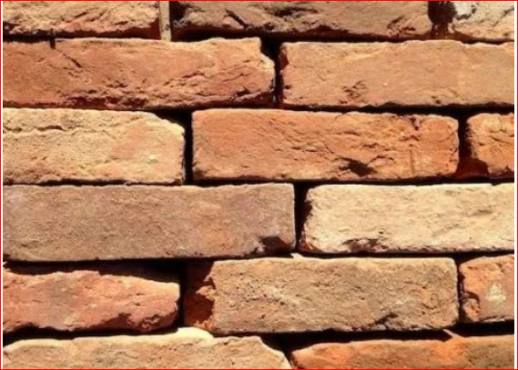


3) BLOATING
This defect observed as spongy swollen mass over the surface of burned bricks. This is caused due to the presence of excess carbonaceous matter and sulphur in brick-clay.

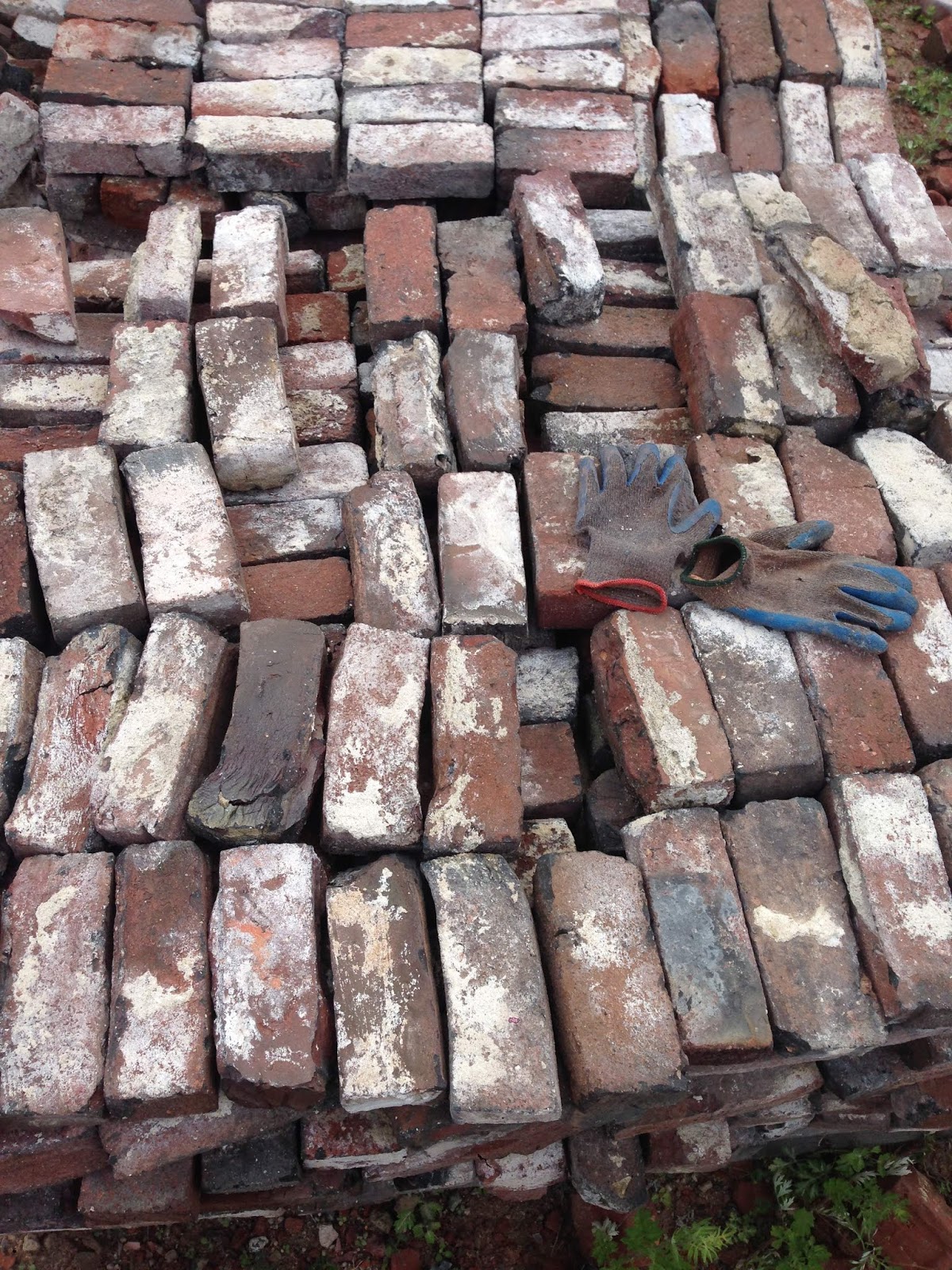


4) BLACK CORE
Presence of bituminous matter or carbon in the brick clay is the cause of this defect. When these matters are not completely removed by oxidation, due to improper burning, the brick results in black core.


5) EFFLORESCENCE

This type of defects in bricks is caused during the absorption of moisture present in the surroundings. If the brick contains alkaline nature(soluable salt). During the contact of moisture with brick, the alkaline substance absorbs moisture. During drying small powder patches will appear on the surface of the brick. Efflorescence will effect in the deterioration of plastering.


6) CHUFFS
The deformation of the shape of bricks caused by the rain water falling on hot bricks is known as chuffs.

7) SPOTS
Iron sulphide, if present in the brick clay, results in dark surface spots on the brick surfaces. Such bricks though not harmful are unsuitable for exposed masonry work.


8) BLISTERS
Broken blisters are generally caused on the surface of sewer pipes and drain tiles due to air imprisoned during their moulding.
9) LAMINATIONS
These are caused by the entrapped air in the voids of clay. Laminations produce thin lamina on the brick faces which weather out on exposure. Such bricks are weak in structure.


10) LIME BLOWING
Disintegration of bricks is the indicator of lime blowing.
If bricks contain lime lump, then lime blowing is expected. The lime absorb water and expand after its exposure to firing. Consequently, lime blowing will take place.
Bricks susceptible to lime blowing can be identified by submerging the brick in water. As a result, the brick fractures and powdery lumps will be exposed.


11) BRICK SPALLING

Irregular portion of the brick break away of fall off.
Heating of water inside brick is the cause of spalling


Comments

Popular posts from this blog

Solving PLAXIS Error Code 103: Understanding and Resolving Load Advancement Procedure Failures

PLAXIS is a widely used geotechnical engineering software for analyzing soil behavior and predicting the response of structures. However, encountering errors during simulations can be frustrating. One such error is Error Code 103, which occurs when the load advancement procedure fails.  In this blog, we will delve into the causes of this error and provide practical solutions to overcome it. So, let's explore how to resolve PLAXIS Error Code 103 and successfully complete your simulations! Understanding PLAXIS Error Code 103: Error Code 103 typically occurs when PLAXIS encounters difficulties while advancing the load during the analysis. It indicates a problem with the load advancement procedure, hindering the successful completion of the simulation. Common Causes of Load Advancement Procedure Failures: a. Numerical Instability: The load advancement procedure can fail due to numerical instability caused by inappropriate model settings, such as unrealistic soil parameters or ...

Understanding Slope Stability and Types of Landslide Movement

Slopes are integral components of both natural landscapes and human-made constructions. However, slope stability can be compromised, leading to slope movements or landslides that pose significant risks to infrastructure and human lives. In this blog post, we will delve into the world of slope stability, exploring the causes of slope failures, different types of landslide movements, and the methods employed to assess and mitigate slope instability. Causes of Slope Failures: Slope failures can be attributed to various natural and human-induced factors. Natural causes include gravitational forces, water saturation, erosion, seismic activity, changes in aquifer levels, volcanic eruptions, and freeze-thaw weathering cycles. On the other hand, human-induced causes encompass activities such as toe excavations, infrastructure loads, machine vibrations, construction of weak embankments or earth dams, and deforestation, which can exacerbate slope instability. Types of Landslide Movements: Lands...

How do you draw contour in Global Mapper? | Global Mapper Software | Google Earth

Find the coordinate of the location using Google Earth Mark the places or  Path Make sure, Latitude/Longitude should be in Universal Transverse Mercator (UTM) Save the location as a KML file and Remember Zone Open Global Mapper Software Open data file (Saved KML file) Select an online data Source as SRTM or ASTER and connect it Analysis Option > Generate Contours (using terrain grid)  Enter the Contour interval and press OK Go to file > Export >  Export vector/ Lidar Format > DWG Download Global Mapper Software for Free