
Power Structure Intake I Types of Power Intake Structure I Hydropower Intake

INTRODUCTION 

The intake structure is a hydraulic structure. Which is used to divert the water from a source (like a reservoir, river) into a conduit (like a canal, tunnel, or pipe). It also supports auxiliary appurtenance (Such as trash rack, fish screens, and bypass devices) and it may include provision for installation of the bulkhead gates or stop-log gates closure devices.


TYPE OF POWER INTAKE STRUCTURE

The Position and location of intake would generally depend upon the type  of development and may be classified under:

A) Run-Of-the river type Intake

B) Reservoir-type intake


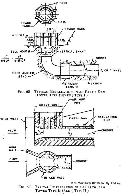
  • Depending on the function, an intake structure may be either submerged or extended in the form of a tower above the maximum reservoir water surface (Fig. 6B)
  • An operating platform is needed to remove trash, maintain and clean fish screens, or install stoplog gates. 
  • Depending on intake requirements, the entrance may be placed vertically, inclined, or horizontally.
  • Conduit entrances should be rounded or bell-mouthed to reduce hydraulic entrance losses.
  • The necessity for a trash rack Structure depends on the size of the Intakes structure, the type of control device used, the nature of the trash burden in the reservoir, the use of the water, the need for excluding small trash from the outflow, and other factors.

The selection of power Intake structures should be based on several factors:

  • Operation (The Reservoir head under which it must operate)
  • Discharge (It Must be handled)
  • The Frequency of reservoir drawdown, trash rack condition in the reservoir (need for cleaning of trash rack)
  • Ice Condition and wave action (From the stability point of view)
  • Depending on its function, An Intake structure may be either submerged or extended in the form of a tower.

IS Code Used For Power Intake Structures 

  • IS: 11625 1986: Criteria for Hydraulic Design of Penstocks
  • IS: 4880 1976: Code of practice for design of tunnels conveying water
  • IS: 11388:2012: Recommendations for design of trash racks for intakes
  • CBIP manuals
  • USBR Manual for Small Dams


Comments

Popular posts from this blog

Understanding Slope Stability and Types of Landslide Movement

Slopes are integral components of both natural landscapes and human-made constructions. However, slope stability can be compromised, leading to slope movements or landslides that pose significant risks to infrastructure and human lives. In this blog post, we will delve into the world of slope stability, exploring the causes of slope failures, different types of landslide movements, and the methods employed to assess and mitigate slope instability. Causes of Slope Failures: Slope failures can be attributed to various natural and human-induced factors. Natural causes include gravitational forces, water saturation, erosion, seismic activity, changes in aquifer levels, volcanic eruptions, and freeze-thaw weathering cycles. On the other hand, human-induced causes encompass activities such as toe excavations, infrastructure loads, machine vibrations, construction of weak embankments or earth dams, and deforestation, which can exacerbate slope instability. Types of Landslide Movements: Lands...

Solving PLAXIS Error Code 103: Understanding and Resolving Load Advancement Procedure Failures

PLAXIS is a widely used geotechnical engineering software for analyzing soil behavior and predicting the response of structures. However, encountering errors during simulations can be frustrating. One such error is Error Code 103, which occurs when the load advancement procedure fails.  In this blog, we will delve into the causes of this error and provide practical solutions to overcome it. So, let's explore how to resolve PLAXIS Error Code 103 and successfully complete your simulations! Understanding PLAXIS Error Code 103: Error Code 103 typically occurs when PLAXIS encounters difficulties while advancing the load during the analysis. It indicates a problem with the load advancement procedure, hindering the successful completion of the simulation. Common Causes of Load Advancement Procedure Failures: a. Numerical Instability: The load advancement procedure can fail due to numerical instability caused by inappropriate model settings, such as unrealistic soil parameters or ...

Understanding Dilation in Overconsolidated Clay Soils during Shearing

In geotechnical engineering, the behavior of soil under stress is a fascinating subject. One aspect that requires careful consideration is the potential for dilation in overconsolidated clay soils during shearing. In this blog post, we will explore the factors influencing dilation and shed light on its significance. So, let's dive in! Understanding Dilation in Overconsolidated Soils: Overconsolidated soils have experienced higher levels of stress in the past, resulting in a denser arrangement of soil particles compared to normally consolidated soils. When these soils undergo shearing, they tend to compress less, and in some cases, they may even dilate.   The Role of Previous Maximum Effective Stress: The key factor that determines the likelihood of dilation is the magnitude of the previous maximum effective stress experienced by the clay soil. This stress represents the maximum stress level the soil has encountered in the past.   Why Dilation Occurs: When the p...